The Model Simulator
Calculating the Simulation
The Model Simulator
Calculating the Simulation
TELE-WORX Making Communications Work...


The model simulator performs a trial in five fundamental steps. First, the model is checked for structural model errors. Next, static calculations are performed. Static calculations are primarily performed on variable values by converters; static calculations may also be performed in modeled stocks, modeled flows and transformers. Dynamic flows are then made in calculated amounts to and from modeled stocks, transformers and fragments. Corrections are applied to stock and flow values to account for configured constraints. Finally, threshold crossings and errors are detected, summarized and reported.
Structural Model Errors
The model is checked for several structural errors such as those that result in unintended permanent infinite or zero stock levels. The simulator searches for the following errors, and instances are reported to the user as errors and summarized to the symbol, fragment, layer and the model:
•an unrestricted flow connecting an unbounded stock and a modeled stock (in either direction)
•an unrestricted flow connecting an unbounded stock and a transformer (in either direction)
•unattached flow lines or variable lines
•a queued stock, custom stock, modeled flow, transformer or factory with no formula (note that the formula for a contained stock can be implicit);
•a converter with an incorrect number of operands (a sum requires at least two operands)
•an external variable from a networked source when no network connection can be established
If structural errors are detected, the model simulator will abort the simulation trial.
Calculations
The following attributes are calculated by the Model Simulator process for each model component for each simulation trial except for unbounded stocks and unrestricted flows:
•VALUE - the result of the primary formula calculation at the current simulation time
- LEVEL is the primary stock value;
- OUTFLOW RATE is the primary flow value and transformer value;
- RESULT is the primary converter value
- OUTPUT is the primary factory value
•VALUE LOG - the log of all VALUE calculations for all trials of the simulation; this log is maintained if GRAPH is enabled (YES) for the model component; optionally, this log is maintained for all model components for playback and export
•THRESHOLD ALARM - threshold crossings that are detected for each threshold attribute defined for the component
•ERROR ALARM - errors that are detected for the component
•SUMMARY STATUS - the most severe status or alarm for the component, fragment, layer and model
Attributes for modeled stocks calculated by the Model Simulator process in addition to the common set:
•NET FLOW - net flow value at the current time = Σt= i outflows - Σt= i inflows
NET FLOW is also logged in the VALUE LOG.
Static calculations are performed in order of dependency:
•external variables are retrieved and interpreted; where external variables are retrieved as an array of values to support a number of trial times, each value is assigned to a trial time
•calculations for converters that operate on external variables and adjusted variables exclusively are processed first
•calculations for converters that operate on internal variables from stocks, flows or transformers exclusively are processed next
•calculations for converters that operate on internal variables from other converters are processed next as those other converters are processed until all converter calculations have been performed
Circular dependencies are identified, and all model components that are circularly dependent declare a CR-ERR error alarm. A circular dependency is detected when a converter is processed twice for the same trial interval and the model simulation ends prematurely.
An explicit order of precedence for static calculations is saved so that subsequent simulations for unaltered models are processed more efficiently.
Corrections
If the user elects for a “Quick” model simulation, CR-INSUF errors are declared when calculated flows exceed flow capacity or stock levels become negative where these constraints have been configured. In this circumstance for “quick” simulations, no corrections are made to the simulation results. The error alarms inform the user that the simulation results are misleading, and summary indications show the user where the model misbehavior is located.
If the user elects for an accurate simulation, a number of corrections are made, and the simulation process may take significantly more time to perform as iterative corrections are performed:
•once all static calculations have been made, a correction is performed for custom flows that have a maximum capacity constraint configured that is less than the calculated flow, and these flow values are revised down to the flow capacity constraint.
•following the correction for insufficient flows, the simulator applies the calculated flow changes to the model and updates the value for each modeled stock connected to a revised flow.
•following the stock updates, a second correction is performed for custom stocks with negative values that have a zero minimum value constraint configured, and these stock values are revised to zero.
This cycle of corrections may be repeated a number of times. The modeled flow fed by a corrected modeled stock is correspondingly adjusted to account for the insufficient stock capacity, and the connected stock fed by the corrected flow is also adjusted in a corresponding manner. This correction cycle is repeated as necessary if a stock value is subsequently adjusted to negative values and the stock is constrained to non-negative values until no further corrections are necessary or no further corrections are possible.
After all corrections have been made, threshold crossings and errors are detected and the corresponding alarms are declared. At this point, the trial is complete, all necessary results are logged, and the next trial commences.
Thresholding
Thresholding is a valuable tool to alert the user to conditions that impact decision-making, model simulation interpretation and simulation error analysis. The user is able to configure thresholds for any flow outflow or stock level during the model building process or at any time during the model simulation process. Custom flows, custom stocks and factories allow thresholding for other attributes as well.
Threshold crossings are logged for the model. The following log is maintained:
•THRESHOLD ALARM LOG
As many as three levels of severity can be assigned to thresholds crossing alarms according to the user’s model design:
•MN (minor)
•MJ (major)
•CR (critical)
Up to six opportunities to threshold are defined:
•MN-range; VALUE ≤ MN-LOW limit, VALUE ≥ MN-HIGH limit (but not MJ or CR)
•MJ range; VALUE ≤ MJ-LOW limit, VALUE ≥ MJ-HIGH limit (but not CR)
•CR range; VALUE ≤ CR-LOW limit, VALUE ≥ CR-HIGH limit
A threshold crossing alarm is declared in each simulation interval that a data value falls in a thresholded region of values that has been defined. The threshold crossing alarm stands (remains) until a new threshold region for data values is entered or until the data value falls in a normal range of values, at which time the threshold crossing alarm is updated or cleared respectively.
The user is not required to utilize thresholds in their model. Further, the user may choose to utilize just several thresholds (but not all). And finally, the user is free to use only the level of urgency that is logically appropriate for the model for each threshold configured.
It is important to note several rules when applying thresholds:
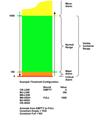
•the order of magnitude is CR-LOW < MJ-LOW < MN-LOW < MN-HIGH < MJ-HIGH < CR-HIGH; this relationship is mandatory; the severity of threshold crossings graduates to more urgent levels (MN to MJ to CR for example) as a flow rate or stock level rises or falls
•a flow’s or a stock’s symbol animation is bounded by EMPTY and FULL and may coincide with a threshold value
An example will help to illustrate the necessary flexibility for thresholds. A petty cash box has a balance on hand as much as $1000, but a balance of $100 or less must be immediately replenished. In this example, a balance more than $1000 is excessive and not correctly represented by the stock animation, and the user is alerted to this circumstance with a minor threshold crossing alarm. A balance of $100 triggers action – a major threshold crossing alarm to the user. The “down- arrow” and “up-arrow” illustrate threshold crossing declarations for the petty cash balance as it falls and rises. Note the deliberate avoidance of a minor threshold defined less that the normal range (MN-LOW), and no major or critical thresholds above the normal range (MJ-HIGH or CR-HIGH) are defined in this example.
The following drawing illustrates a complex assignment of threshold crossing values:
Error Detection and Reporting
An error detection and reporting process advises the user when the model simulator results are misleading or simply incorrect. Symbol border color reflects the severity of an error. Severity is assigned to each error condition as minor, major or critical; the default severity assignments represent the typical relative impact to meaningful simulation results. All error reports are logged for later reference by the user.
Errors are logged for the entire model. The following log is maintained:
•ERROR ALARM LOG
As many as three levels of severity can be assigned to simulation errors:
•MN (minor)
•MJ (major)
•CR (critical)
Errors are reported as “minor”, “major” or “critical”. The criterion for alarm classification is as follows:
•minor errors are animation behavior that might not reflect simulation results
•major errors are simulation results that may be misleading because of the effects of model component constraints
•critical errors are model component malfunction such as a computational error
The simulation is stopped in the event of a critical error.
The following computational errors are detected for all model components:
•invalid operation (e.g., square root of a negative number)
•division by zero
•overflow (a result is too large to be represented correctly)
•underflow (a result is very small (outside the normal range), non-zero, and inexact)
•inexact (the resolution of the result is inadequate to represent the precision of the calsulation)
The following symbols represent stock error conditions; a pictoral addition may also be applied to represent the error condition that is relevant to the configured behavior of the stock.


Stock error indicators include the following conditions
•MN-NEG minor error (default) if a stock has a negative level (under water)
LEVEL < EMPTY and DISPLAY AREA is “YES”
•MN-OVER minor error (default) if stock animation area is insufficient (full level)
LEVEL > FULL and DISPLAY AREA = “YES”
•MJ-INSUF major error (default) if the stock level is insufficient (sucking air)
LEVEL < ZERO and CONSTRAIN ZERO = “YES”, or
LEVEL < CONSTRAINT MIN and CONSTRAIN MIN = “YES”
•MJ-SPILL major error (default) if a full stock is overflowing (spilling the excess)
LEVEL > CONSTRAINT MAX and CONSTRAIN MAX = YES
•CR-ERR critical error (default) if an erroneous behavior or condition is detected such as a computational error; the “bang” demands the user’s attention to the error log
The following symbols represent flow error conditions:


Flow error indicators include the following conditions:
•MN-NEG minor error (default) if a stock has a negative level (under water)
OUTFLOW < EMPTY and DISPLAY AREA is “YES”
•MN-OVER minor error (default) if stock animation area is insufficient (full level)
OUTFLOW > FULL FWD or OUTFLOW < FULL RVS, and
DISPLAY AREA = “YES”
•MJ-INSUF major error (default) if the stock level is insufficient (sucking air)
OUTFLOW < ZERO and CONSTRAIN ZERO = “YES”, or
OUTFLOW < CONSTRAINT MIN and CONSTRAIN MIN = “YES”
•MJ-SPILL major error (default) if a full stock is overflowing (spilling the excess)
OUTFLOW > CONSTRAINT MAX and CONSTRAIN MAX = YES
•CR-ERR critical error (default) if an erroneous behavior or condition is detected such as a computational error; the “bang” demands the user’s attention to the error log
The following symbol represents factory error conditions:


Transformer error indicators include the following three conditions:
•MJ-INSUF IN major error (default) if inflow capacity is insufficient to deliver the required outflow;
•MJ-INSUF OUT major error (default) if the outflow capacity is insufficient (sucking air)
OUTFLOW > CONSTRAINT POS and CONSTRAIN POS = “YES”
•CR-ERR critical error (default) if an erroneous behavior or condition is detected such as a computational error; the “bang” demands the user’s attention to the error log
The following symbol represents factory error conditions:

Factory error indicators include the following condition:
•CR-ERR critical error (default) if an erroneous behavior or condition is detected such as a computational error; the “bang” demands the user’s attention to the error log
A factory may declare other error conditions according to its design.
The following symbol represents converter error conditions:

Converter error indicators include the following condition:
•CR-ERR critical error (default) if an erroneous behavior or condition is detected such as a computational error; the “bang” demands the user’s attention to the error log
The following symbol represents variable error conditions:

External Variable error indicators include the following condition:
•CR-ERR critical error (default) if an erroneous behavior or condition is detected such as a computational error; “file not found” or “404 not found” are unique external variable errors; the “bang” demands the user’s attention to the error log
A fragment allows errors from the modeled constituent components to “bubble up” and be declared. The fragment symbol color reflects the summary state of the fragment’s subset of the model. The following symbol, for example, represents a critical error condition detected in the model subset that the fragment represents:

Custom graphs and tables present the following two error conditions:
•MN-FIT the graph or table does not fit in the print area as formatted
•MN-OOB the data plot lies entirely outside of the bounds of the graph format, orthe tabular data order of magnitude exceeds the formatted number of digits displayed
Summarization
When a threshold crossing is detected, the color of a model component’s symbol border may change according to the model simulation preferences to convey the severity of the threshold crossing alarm:
•green represents a value in a normal range (NL) – no threshold crossed or a return across a threshold to the normal range of data values
•yellow represents a threshold crossing into the minor alarm range of data values (MN)
•orange represents a threshold crossing into the major alarm range of data values (MJ)
•red represents a threshold crossing into the critical range of data values (CR)
When an error is detected, the color of a model component’s symbol border may change according to the model simulation preferences to convey the severity of the error alarm:
•green represents a normal status (NL) – no errors
•yellow represents minor status (MN) – minor errors
•orange represents major status (MJ)– major errors
•red represents critical status (CR) – critical errors
However, only one border color is displayed, and this color corresponds to the most severe of all threshold crossing alarms and error alarms declared for the model component or fragment. This most severe alarm represents the summary status for the model component or fragment.
The summary status is also calculated for each layer of the model according to the most severe alarm declared by the model components on that layer.
The summary status is also calculated for the entire model according to the most severe alarm declared by all the model components on all the layers of the model.
Loading a Model to Simulate
Defining the Model Simulation
Basic Simulator Control Strip Functions
Calculating the Simulation
Structural Model Errors
Calculations
Corrections
Thresholding
Error Detection and Reporting
Summarization
Appendix: The Modeling Process