The Calculator
An Introduction to the SD Model
The Calculator
An Introduction to the SD Model
TELE-WORX Making Communications Work...


The following diagram introduces various elements of a System Dynamics Model and illustrates the relationship between the model’s data structures:
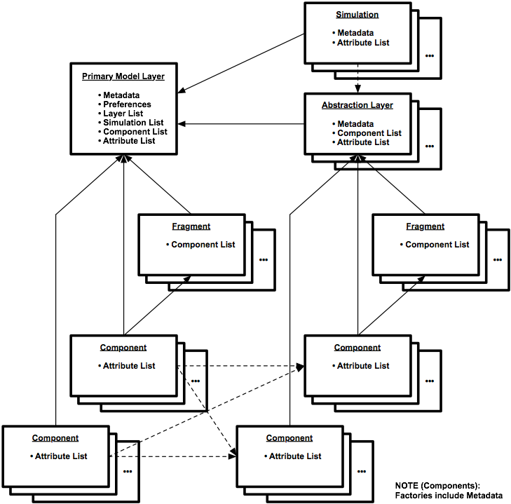
In this drawing, the following elements are introduced:
•Component - a model component is a basic system dynamics function block such as a stock or flow
•Fragment - a fragment is a convenient collection of model components – a subset of the model
•Primary Model Layer - the primary model layer holds the fundamental model – this fundamental model may be the entire model, or it may be the core part of the model to which other parts of the model may refer for internal variable values
•Abstraction Layer - an abstraction layer is a separate layer of the model that facilitates model partitioning, simulation partitioning and collaboration; an abstraction layer refers to the primary model layer for interval variable values
•Simulation - a simulation of a system dynamics model is the sum total of calculations specified by the model over a sequence of time intervals; a simulation also includes a collection of attributes that establish boundary conditions, initial states, output options and other simulation options
•Metadata - metadata is a preamble of information that provides details such as a name, version, information model compliance, model owner, creation or revision date, an abstract and other useful information
In this drawing, a solid line and arrow identifies containment – the primary model layer contains components. A dashed line and arrow identifies a less significant relationship – an abstraction layer model component makes use of a primary model layer component’s attributes such as its value.
In this drawing, it is important to note several details. All model elements have a relationship with the primary model layer either directly or indirectly. A fragment has many of the same characteristics as the primary model layer such as extensive metadata. Components that belong to a fragment also belong to the model layer. Fragments are treated like components in many ways; fragments may contain fragments, and any layer may contain fragments.
A System Dynamics model is fundamentally based upon stocks of “goods” and flows of a “good” between stocks over time. Flows move a calculated quantity of a “good” between stocks in each unit of time during the model simulation. Stocks and flows are typically connected in a “causal loop” to model cycles of cause and effect relationships and dominant constructive and destructive forces in the system. Stocks and flows have limitations, and flows have controls. This modeling technique may also employ feedback in the model to characterize the dynamic behavior of a system and capture real-world behaviors that are relevant to the model objectives.
A system dynamics model consists of a small set of model components:
•Stocks - goods storage with flows of the good in and out
•Flows - goods transport between stocks
•Transformers - goods transformation from one or more good to another
•Converters - a numerical calculator function chosen from a comprehensive set
•Variables - internal, external and user provided model values
•Factories - functional building blocks – macros – of many model components
A model component has the following characteristics:
•Names - a user-assigned label and also a computer-assigned label
•Type - the type and subtype of model component
•Symbol - a basic shape with visual cues for subtype, value, status and activity
•Location - the symbol’s coordinates on the model image
•Interfaces - the set of connections to other model components that are allowed
•Connections - direct associations with other model components
•Indicators - values, summary, animation, mouse overs, graphs and tables
•Attributes - the set of characteristics that are configured by the user
•Formulas - the mathematical formulas that operate on the connected components
•Value - the attribute that is calculated by the component from formulas
•Cost - the per interval / per unit cost
•Alarms - threshold crossings, illegal operations or model malfunctions
•Security - the permission for the user to edit configurable characteristics
•Notes - simple text generated by the user and placed anywhere to explain things
•Other Behaviors - characteristics in addition to indicators, interfaces and errors detected
The model displays the summary, or the most severe status or alarm level for the entire model, for each layer, for each fragment, and for each component:
•Summary Status - static (ST – the model simulator is idle)
- not alarmed (NL – the model, fragment or component status is normal)
- alarmed (a MN minor, MJ major or CR critical – a threshold crossing or an error has been detected)
•Threshold Alarms - threshold crossings between normal, minor, major and critical ranges
•Error Alarms - errors that produce misleading simulation results or reflect model malfunctions or calculation errors
The model can be layered into “abstractions”. The user can create an abstraction layer to facilitate analysis of a model without the distraction of the primary model in the application foreground. The following abstraction layer is defined, and the user can define other abstraction layers:
•General Abstraction Layers - separate model layers that are useful for focused analysis of the model
•Cost Abstraction Layer - all modeled stocks, modeled flows, transformers and factories have a cost attribute that can be defined and accumulated by a cost account finance factory in a separate model layer
The model can be augmented with components that simplify its display and simulation
•Fragments - convenient subsets of the model represented by a single symbol
•Scripts - a small program to perform specified actions in a sequence; a script is dependent on the hardware and software platform in use, and it is not discussed further in this document
An Introduction to System Dynamics Models
Basic Calculator Architectures
Conventional Calculator Functionality
Appendix: The Modeling Process